Dies ist eine alte Version des Dokuments!
Warning: Undefined array key 1 in /is/htdocs/wp1019470_OPI92FFHXV/www/wikiLehre/lib/plugins/imagebox/syntax.php on line 24
Warning: Undefined array key "h" in /is/htdocs/wp1019470_OPI92FFHXV/www/wikiLehre/lib/plugins/imagebox/syntax.php on line 55
Warning: Undefined array key 1 in /is/htdocs/wp1019470_OPI92FFHXV/www/wikiLehre/lib/plugins/imagebox/syntax.php on line 24
Warning: Undefined array key "h" in /is/htdocs/wp1019470_OPI92FFHXV/www/wikiLehre/lib/plugins/imagebox/syntax.php on line 55
Warning: Undefined array key 1 in /is/htdocs/wp1019470_OPI92FFHXV/www/wikiLehre/lib/plugins/imagebox/syntax.php on line 24
Warning: Undefined array key "h" in /is/htdocs/wp1019470_OPI92FFHXV/www/wikiLehre/lib/plugins/imagebox/syntax.php on line 55
Warning: Undefined array key 1 in /is/htdocs/wp1019470_OPI92FFHXV/www/wikiLehre/lib/plugins/imagebox/syntax.php on line 24
Warning: Undefined array key "h" in /is/htdocs/wp1019470_OPI92FFHXV/www/wikiLehre/lib/plugins/imagebox/syntax.php on line 55
Warning: Undefined array key 1 in /is/htdocs/wp1019470_OPI92FFHXV/www/wikiLehre/lib/plugins/imagebox/syntax.php on line 24
Warning: Undefined array key "h" in /is/htdocs/wp1019470_OPI92FFHXV/www/wikiLehre/lib/plugins/imagebox/syntax.php on line 55
Warning: Undefined array key 1 in /is/htdocs/wp1019470_OPI92FFHXV/www/wikiLehre/lib/plugins/imagebox/syntax.php on line 24
Warning: Undefined array key "h" in /is/htdocs/wp1019470_OPI92FFHXV/www/wikiLehre/lib/plugins/imagebox/syntax.php on line 55
Warning: Undefined array key 1 in /is/htdocs/wp1019470_OPI92FFHXV/www/wikiLehre/lib/plugins/imagebox/syntax.php on line 24
Warning: Undefined array key "h" in /is/htdocs/wp1019470_OPI92FFHXV/www/wikiLehre/lib/plugins/imagebox/syntax.php on line 55
Warning: Undefined array key 1 in /is/htdocs/wp1019470_OPI92FFHXV/www/wikiLehre/lib/plugins/imagebox/syntax.php on line 24
Warning: Undefined array key "h" in /is/htdocs/wp1019470_OPI92FFHXV/www/wikiLehre/lib/plugins/imagebox/syntax.php on line 55
Warning: Undefined array key 1 in /is/htdocs/wp1019470_OPI92FFHXV/www/wikiLehre/lib/plugins/imagebox/syntax.php on line 24
Warning: Undefined array key "h" in /is/htdocs/wp1019470_OPI92FFHXV/www/wikiLehre/lib/plugins/imagebox/syntax.php on line 55
Warning: Undefined array key 1 in /is/htdocs/wp1019470_OPI92FFHXV/www/wikiLehre/lib/plugins/imagebox/syntax.php on line 24
Warning: Undefined array key "h" in /is/htdocs/wp1019470_OPI92FFHXV/www/wikiLehre/lib/plugins/imagebox/syntax.php on line 55
Inhaltsverzeichnis
2015 Öhlke
| Title | Realization and optimization of robotic hopping motions using bio-inspired virtual model control |
|---|---|
| Author | Jonathan Öhlke |
| Last changes | 25.04.2016 |
Introduction
Legged locomotion can be divided in three locomotion sub-functions [1]: bouncing, leg swinging, balancing. Bouncing or hopping (axial leg function), which is the focus of this study, describes the elastic rebounding of the stance leg during ground contact to counteract gravity [2]. Template models [3] - although highly simplified in structure - are a very useful tool to understand how these sub-functions are controlled and coordinated, both in nature [3] and legged robots [4]. Hopping is the only gait that is feasible with one leg and can be considered as a prerequisite movement for running. In vertical movement, the only required locomotor sub-function is hopping. There are a lot of hopping robots in recent research. In [5] a segmented robotic leg is presented which works with an actuated hip joint and a passive compliant knee joint. The proper tuning of the stiffness of the knee joint leads to an improved energy efficiency. Another segmented robotic leg is presented in [6]. The focus lies on a compliant actuator with a stiffening spring. Experiments show an extended performance in comparison with an actuator without compliance. A segmented robotic leg of a bigger scale is presented in [7]. The research on this leg, that should be used for running and walking robots, also focuses on a compliant actuation system and a design that supports natural dynamics. A drawback is given by the fixed values of the used springs. Also, some older projects cope with (nonsegmented)hopping robotic legs and methods that improve the efficiency of the mechanisms (see [8], [9]). All of them try to improve the energy efficiency of compliant segmented or straight robotic legs through different methods. Applying conceptual models as templates for control may be a useful approach to fill the gap between human experiments and robot control [3]. For this, abstraction is the key feature in simplifying human locomotion problems, finding a solution and extending the simple control to the complex model, following the approach of “template and anchor” [3]. A spring-loaded inverted pendulum (SLIP) model [2] is a template model explaining the axial leg function in walking and running [10]. Extended SLIP models, like ESLIP [11] or the variable leg spring (VLS) model [12], describe leg spring adjustments (stiffness, rest length) during stance phase. They provide better representations of human bouncing behavior, which can be used for the control of a system. This paper extends the bio-inspired template based control implemented on the original 1D MARCO-Hopper [13] to the new MARCO-Hopper II robot with segmented leg and knee extensor. The setup with a modular actuation system, enables the comparison of different actuator designs for realizing bio-inspired hopping movements. Regarding this goal, a virtual model control (VMC) [14] for mimicking SLIP based hopping by emulating a virtual spring behavior on MARCO-Hopper II (called hereafter MARCO II), is employed. The behavior of the system is influenced by the manipulation of the parameters of the virtual spring. Section II shows the development of this control strategy and the test-bed. In Section III simulation and experimental results are compared, which show comparable performance of MARCO II to human hopping and SLIP based hopping. Section IV gives an insight in consequences and possible future approaches resulting from this work.
Methods
In this paper, template models are employed to fill the gap between biological and robotic locomotion. Human hopping properties can be explained by a spring mass model [2], [11], [12]. To mimic this behavior with a segmented structure a connection between the SLIP model and the multi-body system has to be found. The virtual model control is utilized to produce SLIP-like vertical hopping with MARCO II. The idea of virtual model control is to emulate virtual components behavior with real actuators. Hence, the required knee torque, as a function of the knee angle, is calculated to generate a spring-like (linear) relation between the axial leg force and the length of the virtual leg (defined by a line from hip to foot). The approach is to move step by step from the SLIP model (spring loaded inverted pendulum: a point mass atop a mass-less spring) [2] (Fig. 1 b), over a segmented leg with an attached single mass (Fig 1 c), to a complete multibody simulation model of MARCO II, as shown in Fig. 1 d.

Here the actuator and transformation dynamics and also system losses (e.g., in the drive-train and the cable) are taken into account. Each system with ascending complexity is controlled to behave like a SLIP model. Finally the controller is implemented on the hardware setup. As a result a bioinspired hopping controller on a two-segmented robotic leg can be implemented.
Test-bed MARCO Hopper 2
In the SLIP model as a conservative model there is no need for the compensation of energy losses. On the opposite, stable hopping without energy management is not achievable in a real robotic system [13]. To investigate different energy management methods inspired from human hopping motions, a test-bed called MARCO (Mechanical adjustable reflexive compliant) Hopper was developed [15] (Fig. 2[a]).


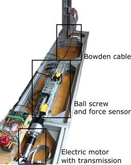
Since the structures of MARCO, as the predecessor of MARCO II, and the SLIP model are very similar, the applicability of the developed control strategies on more complex, segmented multi-body structures was an open question. A segmented robotic leg comes closer to the human role-model. The application of bio-inspired control strategies on such a testbed is another step to successful biomimetics. In order to respond this question a new version of that robot, called MARCO Hopper II (Fig. 2[b]) was developed at TU Darmstadt, Germany. MARCO II consists of two links mimicking shank and thigh (with length $l_\text{l}$) that are connected by a roller bearing (knee joint). A mass ($m_1$) at the top point resembles the body. The knee is actuated via a cable (with stiffness $k_\text{c}$) attached to a pulley (with radius $r$). The actuator of the system in combination with a transmission and a ball screw is placed outside of the leg to separate its inertia from the moving parts of the leg (Fig. 2[c]). The positions of the hip and the foot are calculated with the angular data of the thigh measured by an IMU (inertia module unit) and a potentiometer position sensor, respectively. The ground reaction force and the actuator force (in the drivetrain) are measured with strain gauge force sensors. Force sensing happens only for the analysis of the system. Only the position data is required to mimic a spring-mass behavior with the two-segmented leg of MARCO II. The drive-train can be adapted to different actuation systems such as Serial Elastic Actuation (SEA) or other soft actuation concepts. In the current rigid version, a geared electric motor with the maximum power of 200 W and a maximum current of 10.5 A is utilized. More details about the MARCO II hardware setup are described in the table below.
| Properties of the test bed | |
|---|---|
| motor | maxon EC-4pole, $P$=200 W |
| transmission | maxon GP 42 C, $i$=91/6) |
| ball screw | item KGT VK14, $i$=314 |
| length segments leg | $l_\text{l}$=0.25 m |
| mass at the hip, „body mass“ | $m_1$=1.1 kg |
| mass of a segment | $m_2$=0.1 kg |
| mass of the foot | $m_3$=0.3 kg |
| spring rate cable | $k_\text{c}$=556650 N/m |
| radius pulley | $r$=0.034 m |
| mass SLIP model | $m$=1 kg |
| basic virtual stiffness | $k_0$=65.4 N/m |
| basic injected energy | $\Delta W$=5 J |
Control Concept
With the virtual model control (VMC) approach [16], the effects of a spring with the stiffness kv between hip and foot are mimicked, as shown in Fig. 1 c. The torque t at the knee is controlled in a manner to have the same effect on the leg as a spring would have. This connection is given by the comparison of the dynamic equations of both systems. It is calculated as follows:
\begin{equation} \tau=2\text{ }\cos\left(\frac{\phi}{2}\right)l_{\text{l}}k_{\text{v}}(l_0-x_{\text{h}}+x_{\text{f}})\text{ (1)} \end{equation}
in which, $\phi$, $l_0$, $x_{\text{h}}$ and $x_{\text{f}}$ are the knee angle, the virtual spring rest length, the positions of hip and foot, respectively. This approach is valid for a mass-less segmented leg with one mass at the hip $m_1$, shown in Fig.. Although this relation for the complete model of MARCO II including distributed masses in the legs (shown in Fig. 1 (d)) is more complex, the same principle will be held. A system with the masses of the body, $m_1$, the leg segment $m_2$ and the foot $m_3$ mimic the behavior of a single mass oscillator $m$ (see Fig. 1), if the torque $\tau$ is generated with the following law:
\begin{equation} \tau = 2\cos\left(\frac{\phi}{2}\right) l_{l} \left(\frac{k_{v} (l_0-x_h+x_f) }{m} \left(m_1 + \frac{3}{4} m_2\right) + \frac{m_2g}{4}\right) \text{ (2)} \end{equation}
The desired hopping condition (i.e. hopping height) can be determined by tuning the virtual spring parameters (rest length $l_0$ and the stiffness $k_{\text{v}}$). In all trials (simulation and experiments) the initial condition ($x_{h} = x_0$ and $x_{f}=0$) is a compressed position with zero initial speed (called MC, maximum compression). The virtual spring rest length is adjusted to the maximum leg length of MARCO II; $l_0=0.5$ m. Starting from a fixed MC, this rest length results in the highest hopping height for each stiffness. Thus, the hopping height can be adjusted by $k_{v}$. In the SLIP model, the hopping frequency is determined by $\omega=\sqrt{\frac{k}{m}}$, which is the natural frequency of the system. Hopping is given when the foot leaves the ground. This condition is given when the hip position and hence leg length get higher than the rest length of the virtual spring. To satisfy this condition, the energy stored in the spring in the initial condition ($x_0$) should be higher than $mg(l_0-x_0)$ and thus:
\begin{equation} k_{v}>\frac{2mg}{l_0-x_0} \text{ (3)} \end{equation}
Satisfying this condition besides Eq. (1), controls a desired hopping motion in a SLIP model and more complex multi-body models. It is notable that like the SLIP model, in which the spring just pushes (positive force in upward direction), in MARCO II the actuator can only extend the knee through pulling the cable connected to the pulley at the knee (similarly, upward force direction).
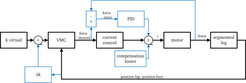
A block diagram of the control approach is presented in Fig. 3. The control concept is shown with black lines, in which the VMC uses the positions of the hip and foot (their difference is the current length of the virtual spring) and the virtual stiffness to find the desired knee torque. To command the required knee, the corresponding current is calculated using a motor model. This can be considered as a feed-forward control term since there is no feedback considered for tracking the desired torque. The only feedback is the actual leg length for determining the related torque. An extended control approach is shown via the blue lines in Fig. 3. This additional feedback loop is able to use measured force (the force attacking the cable) to adapt the virtual stiffness. As impact through ground contact and system friction cause losses it is possible to compensate them with complementary control terms to enhance the hopping performance. For the experiments shown here the force-feedback is not used, but the possibility of enhancing the performance with a force-feedback loop is given. Because at every hop the impact at ground contact and friction in the system causes losses, a kind of energy management is required to achieve stable hopping in the real system. The first option is to calculate the lost energy and to inject the exact amount by increasing the motor current. Since the model is is complex and has several uncertainties, calculating the precise amount of losses is not practicable. It was shown that for SLIP-based control of the MARCO-Hopper, injecting a constant amount of energy in each bounce results in stable hopping [13]. The strategy for injecting energy in this work is to change the virtual spring stiffness during the movement in two different ways.
Bang-bang control of virtual stiffness
In this approach, the virtual spring stiffness $k_{\text{v}}$ switches between zero and a positive value $k_{\text{v}}$ satisfying Eq. (3). The system initiates at the lowest position $x_0$ with a vertical speed equal to zero and with a nonzero virtual stiffness $k_{\text{v}}$. During the upward motion the stiffness switches to zero when the leg is completely stretched (leg length is equal to the rest length); which means that the required torque at the knee becomes zero. The inertial forces/torques of body, thigh, and shank make the robotic leg leave the ground. Because the virtual stiffness is still zero the structure can to fall freely downward after reaching the apex point. The virtual spring stiffness switches back to $k_v$ when the hip point reaches the lowest point. At this point the virtual spring reaches maximum compression (MC). With this approach the highest possible amount of energy with fixed values for spring rest length $l_0$, maximum stiffness $k_v$ and initial hip position $x_0$ is injected [13]. In other words, if a fixed amount of energy should be injected, this is the minimum required change in the stiffness that is necessary if $x_0$ and $l_0$ are fixed. However, there is a discontinuity in the required axial force (respectively in knee torque) when the virtual spring stiffness switches from zero to $k_v$ at MC. A discrete change in the desired knee torque is not desirable for the actuator and is also not biologically inspired. So the second approach to smooth the knee torque pattern is presented. The switching from $k_v$ to zero at the apex point does not result in a discrete jump of the knee torque. The virtual spring force is zero when the leg length is equal to the rest length $l_0$.
Continuous change of the spring stiffness
The linear stiffness increment of virtual spring stiffness suggested by Kalveram et al. for MARCO-Hopper [13] is used here. In this approach, a certain amount of energy is injected into the system during each hopping cycle to compensate losses and to reach a certain hopping height. It was shown that adding a fixed amount of energy $\Delta W$ to the hopper system can converge to a periodic stable vertical hopping if $\Delta W$ is greater than an unknown but existing threshold. The threshold can be determined, if the losses during a hopping cycle are known. Perturbations of the motion and changes in mechanical parameters make the prediction of the losses difficult. So the injected amount of energy is adjusted during experiments to achieve a hopping motion. The adjustment of the spring stiffness starts with $k_v=k_0$ at MC ($x_0$) and is increased by adding the additional term $\Delta k$ (see Fig. 3). $k_0$ serves as a hopping condition extracted from the SLIP model, while $\Delta k$ compensates losses and unmodeled effects. \begin{align} \begin{split} k_{\text{v}}=&k_0+\Delta k\\ \text{with: }\Delta k=&\frac{6\text{ }\Delta W}{(l_0-x_0)^3} ((x_{\text{h}}-x_{\text{f}})-x_0) \text{ (4)}\\ \end{split} \end{align} The additional term in the stiffness calculation $\Delta k$ has a linear relation to the difference between the actual leg length ($x_{\text{h}}-x_{\text{f}}$) and the initial hip height ($x_0$). Thus, during moving upward this amount will increase linearly. The proportionality factor that includes $\Delta W$ derives from a biologically reasonable mathematical formulation of the additional force acting in the manipulated spring. In [13] it was shown that with this formulation the injected amount of energy $\Delta W$ is equal to the same amount of energy injected in a SLIP model if the spring reaches the rest length during each hopping cycle. For the derivation of this formulation see [13]. The virtual stiffness is set to zero during the downward motion similar to the bang-bang approach. In this approach the fixed term of the stiffness ($k_0$) is found from the SLIP model. It is the stiffness that leads to a movement reaching the rest length of the virtual spring. The injection of a fixed amount of energy $\Delta W$, by increasing the stiffness by the term $\Delta k$ during the travel of the hip from $x_0$ to the rest length, determines the hopping height. A value for the injected energy was found iteratively by experiments with the test-bed. The tested range of values is between 1-8 J.
Simulation model
In order to implement a human-inspired hopping control on the hardware setup, several simulation models with ascending complexity as shown in Fig. 1 have been developed. The SLIP model is used as a benchmark and as the template for desired hopping behavior. A model of a segmented leg without details of hardware setups (e.g., drive train) helps to investigate the applicability of the control concept to the segmented leg mechanism. Then, with the detailed multi-body model the controller is validated to be implemented on the real system. With this model, the influence of the actuation mechanism on the performance of the controlled system can be shown, to find solutions coping with issues expected from the hardware setup. For simulation models, Matlab Simulink and SimMechanics with the ODE23 solver are used. Friction forces were modeled with an adapted model basing on a Stribeck-model presented in [17]. The ground impact model bases on a realistic non-linear spring-damper model presented in [5].
The latest model and the simulation parameters are downloadable below.
Results and discussion
Subsequently, the results of applying the bio-inspired hopping control on different levels of simulation models and a hardware setup are presented. Stable hopping with MARCO II is depicted and compared with a simulated multi-body system to show the validity of the model which is comparable to human hopping experiments.
Performance of the control approach
Starting from a desired hopping motion of the SLIP model, a desired torque in the segmented leg mechanism without drive-train can be found (see Eq. (2)). This torque pattern can ideally mimic similar hopping if there are no losses or they can be estimated and compensated. The model of the segmented leg helps to understand the basic multi-body dynamics of MARCO II and is the counterpart to the SLIP model. The next step is to evaluate the control on a multi-body model with drive-train (the complete model of MARCO II). The complexity of the model increases when including losses, mass distribution, transformation and other limitations. Only the basic parameters of the SLIP model (e.g., initial conditions, spring rest length and basic stiffness $k_0$) are considered in control to avoid this complexity. In Fig. 4 a comparison between a single hop performed with the SLIP model and with the multi-body model of MARCO II is shown.
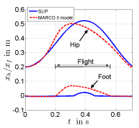

The injected energy is $\Delta W=5~J$ and the parameters are set to values found in the hardware setup or in identification phase ($m_1, m_2$ and $m_3$, bearing friction coefficient, the cable efficiency, the impact model at touchdown and also at the knee stop etc.). The results show that both movements have the same duration and reach comparable apex heights (see Fig. 4). In the SLIP model the movement is symmetric whereas in the multi-body system the robot moves upward faster than falling downward. The reason is the asymmetric implemented stiffnesses in these two phases (see Fig. 4 b). During the upward movement energy is injected by increasing the virtual stiffness of the system. This energy might be even higher than losses in this phase. During falling the virtual stiffness is equal to zero and counteracted by forces like friction.
Comparison with human hopping
In Fig. 5 a the hip position and the ground reaction force $F_{\text{GRF}}$ are shown for four hops of the segmented leg model (without drive train).


This movement, which is generated based on the SLIP model, is stable and comparable to the human hopping motions shown in Fig. 5. The movement patterns of the hip position (frequency about $f=1,5$ Hz and the form) show comparable results for the simulation (a) and the experiment with human subjects (b) (adopted from [13]). Also the ground reaction force patterns are similar. Absolute values of the amplitudes come not close to each other, because the masses and the dimensions also differ between a human and the model of MARCO II. None the less this comparison shows, that if the actuator can generate the desired torque at the knee joint, human-like hopping is achievable with the proposed bio-inspired control approach. However, with the constraints in the hardware setup, similar hopping conditions are not achievable with the current version of MARCO II: results obtained by using the same parameters and the complete multi-body model of MARCO II with drive train are shown in Fig. 5 a. Here the complete simulation model (solid line) and an experiment with MARCO II (dashed line) are compared. With the complete simulation model stable hopping can be achieved and the resulting motion comes close to the previous one, shown in Fig. 5 a. Hopping height and hopping frequency are decreased. This happens because of limitations in the drive train, which prevent the actuator to produce the desired knee torque. Actuator limitations decrease the quality of the control in the actual version of MARCO II. From another point of view the produced hopping can be considered as human-like hopping (because it can be produced by a SLIP model) with different resulting conditions (e.g., frequency). Therefore, doing human hopping experiments with a larger range of hopping conditions or releasing the hardware constraints may help find more similar behavior in humans and the robot.
Experimental results of control ideas
Also in Fig. 6 simulation results (solid line) are compared to experimental results with MARCO II (dashed line).
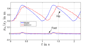
After the tuning of the control parameters in the model and the test-bed, similar hopping behaviors are achieved. The actuator system reaches its performance limitations during the experiments. For higher hopping results some changes on the hardware have to be made. Regarding imprecise torque control of the actuator, which suffers from noisy measurement of the torque, the internal torque control mechanism and inherent delay of the sensory-motor system, the results are not precisely reproducible in the simulation model. To resolve this issues, some modifications of the structure (regarding the friction), more precise sensors and a more powerful motor-controller are required. However, stable hopping can be achieved with applying the simple proposed control approach on the existing hardware setup. Therefore, the applicability of the bio-inspired control approach on the real system is demonstrated by this results.
Discussion
This paper contributes on using bio-inspired template models that describe human locomotion to control robotic systems focusing on the imitation of human hopping. To overcome the gap between biological and robotic locomotor system design and control, axial leg function is modeled by a virtual spring between hip and foot and utilized to generate knee torques that facilitate stable hopping.
Considering an actuator that only mimics a knee extensor shows that this bio-inspired feed-foward locomotion control approach is feasible in hopping and efficiently exploits system dynamics and interaction with the environment. Through the only variable parameter, virtual stiffness $k_{\text{v}}$ or injected energy $\Delta W$ respectively, the hopping motion can be adjusted. Due to this and the reduced number of required sensor data (positions of the leg segments), the control approach is easy to understand, realize, and tune.
Limitations in achieving the simulated performance within the test-bed are due to mechanical issues of the real system. Although the preliminary results shown in this paper might not be optimal, they show that the control approach is promising for further investigation and implementation in various robotic systems. Such might benefit from simplifying control by using template models in legged locomotion.
The applicability of the template-based control using VMC in producing stable human-like movement with a simple mechanism of pulling a cable, could further be extended to more complex systems. Future works might transfer it to robots with musculoskeletal structures or assistive devices.
Model files
In the downloadable file you find the developed models and all used parameters. It has been designed in Matlab R2013a.
Literatur
[1] Seyfarth, A., Grimmer, S., Maus, H.-M., Haeufle, D., Peuker, F., Kalveram, K.-T. (2012). Biomechanical and Neuromechanical Concepts for Legged Locomotion. Biomechanical and Neuromechanical Concepts for Legged Locomotion, Routledge Handbook of Motor Control and Motor Learning.
[2] Blickhan, R. (1989). The spring-mass model for running and hopping. Journal of Biomechanics.
[3] Full, R. J., Koditschek, D. (1999). Templates and anchors: Neuromechanical hypotheses of legged locomotion on land. Journal of Experimental Biology, vol. 22, pp. 3325–3332.
[4] Raibert, M. H. (1986). Legged Robots that Balance. MIT Press, Cambridge.
[5] Vu, H., Pfeiffer, R., Iida, F., Yu, X. (2015). Improving energy efficiency of hopping locomotion by using a variable stiffness actuator. IEEE/ASME Transactions on Mechatronics, vol. PP, no. 99, pp. 1–1.
[6] Vanderborght, B., Tsagarakis, N., G., Van Ham, R., Thorson, I., Caldwell, D., G. (2011). MACCEPA 2.0: compliant actuator used for energy efficient hopping robot Chobino1d. Autonomous Robots, vol. 31, no. 1, pp. 55–65.
[7] Hurst, J., Rizzi, A. (2008). Series compliance for an efficient running gait. IEEE Robotics & Automation Magazine, vol. 15, no. 3, pp. 42–51.
[8] Ahmadi, M., Buehler, M. (1999). The ARL monopod II running robot: Control and energetics. Robotics and Automation, Proceedings IEEE International Conference on, vol. 3. IEEE, pp. 1689–1694.
[9] Zeglin, G., Brown, B. (1998). Control of a bow leg hopping robot. Robotics and Automation. Proceedings. IEEE International Conference on, vol. 1. IEEE, pp. 793–798.
[10] Geyer, H., Seyfarth, A., Blickhan, R. (2006). Compliant leg behaviour explains basic dynamics of walking and running. Proceedings of the Royal Society B, vol. 273, no. 1603, pp. 2861–2867.
[11] Ludwig, C., Grimmer, S., Seyfarth, A., Maus, H.-M. (2008). Multiple-step model-experiment matching allows precise definition of dynamical leg parameters in human running. Journal of Biomechanics, vol. 42, pp. 2472–2475.
[12] Riese, S., Seyfarth, A., (2013). Stance leg control: variation of leg parameters supports stable hopping. Bioinspiration and Biomimetics, vol. 7, no. 1.
[13] Kalveram, K.-T., Haeufle, D., F., B., Seyfarth, A., Grimmer, S. (2012). Energy management that generates terrain following versus apex-preserving hopping in man and machine. Biological cybernetics, vol. 106, no. 1, pp. 1–13.
[14] Pratt, J., Chew, C.-M., Torres, A., Dilworth, P., Pratt, G. (2001). Virtual model control: An intuitive approach for bipedal locomotion. The International Journal of Robotics Research, vol. 20, no. 2, pp. 129–143.
[15] Seyfarth, A., Kalveram, K.-T., Geyer, H. (2007). Simulating musclereflex dynamics in a simple hopping robot. Autonome Mobile Systeme 2007. Springer, pp. 294–300.
[16] Pratt, J., Dilworth, P., Pratt, G. (1997). Virtual model control of a bipedal walking robot.Robotics and Automation. Proceedings., 1997 IEEE International Conference on, vol. 1. IEEE, pp. 193–198.
[17] Kraeamer, A., Kempkes, J. (2014). Modellierung und Simulation von nichtlinearen Reibungseffekten bei der Lageregelung von Servomotoren.