Inhaltsverzeichnis
Trajectory generation for exoskeletons
| Modul-Icon | 3M Seminar 2015 |
|---|---|
| Veranstaltung | 3M-Seminar 2015 |
| Autor | Willi Duttenhoefer, Patrick Lerge, Jannik Abbenseth, Nicolai Ommer |
| Bearbeitungsdauer | 10h pro Person |
| Präsentationstermin | - |
| Zuletzt geändert | 24.07.2015 |
Introduction
In this project we ported the movement trajectory recorded with the VICON system to the KIT-EXO-1. The KIT-EXO-1 is an exoskeleton leg consisting of a knee joint and an ankle joint. We only used the knee joint. The VICON system is a camera system that tracks (human) motion. We used a squat movement from the KIT Motion Data Base in the MMM XML format.
The project consisted of two steps: First, we had to gather the movement data. The challenge is to convert the movement so that it is executable by the exoskeleton. The movement is limited by the maximum angle of the joints and the maximum velocity of the motor. We will show different approaches to cope with these limitations. Second, we had to execute the modified trajectory using Matlab.
Getting the physical limits for the exosceleton
The KIT-EXO-1 is not able to copy the human knee. The maximum angle for the knee joint of the KIT-EXO-1 is about 65° whereas the human knee can easily reach about 130°. Given only 30V operating voltage and the voltage constant for the motor one can calculate the maximum angular velocity for the motor. For KIT-EXO-1 the maximum rounds per minute can be calculated: ;#; \begin{align*} K_t &= \text{const} = 5.497 \frac{\text{V}}{\text{krpm}} \\ U_{max}&= 30\text{V} \\ V_{max} &= \frac{U_{max}}{K_t} \approx 5.5 \text{krpm} \end{align*} ;#;
We decided to convert any given trajectory to motorcounts. Therefore we had to determine a function $y[motorcounts] = f(x [°])$. By measuring the angle and corresponding motorcounts for the maximum and minimum positions we had two datapoints which allowed a linear fit. Checking intermediate points revealed the function $f(x)$ can be assumed linear within our measurement errors. With $f(0°)=0\text{motorcount}$ and $f(65°)=551800\text{motorcount}$ the resulting function is: ;#; \begin{align*} y=f(x)=ax+b=8489\frac{\text{motorcount}}{°}x \end{align*} ;#; The maximum speed of the motor in motorcounts per second can be calculated by: ;#; \begin{align*} v_{max} = 5.5 \cdot 1000\frac{\text{revolution}}{60 \text{s}} * 5670 \frac{\text{motorcounts}}{\text{revolution}}=519750\frac{\text{motorcounts}}{\text{s}} \end{align*} ;#;
Trajectory generation for a squat movement
We decided to execute a squat with the exoskeleton, so we chose the squat03 from the KIT motion database:
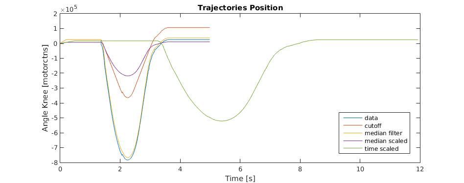
The following figures show the original data as well as different approaches to port the trajectories to the exoskeleton. Trajectories are defined over position and velocity. We also have access to the acceleration, but it turned out to be too noisy to be usable for us and only wanted to send position and velocity to the motor controllers anyway.

Modifying trajectory to cope with limits of exoskeleton
The original trajectories can not be executed directly, as the maximum angle of the knee joint and the maximum velocity is too large for the exosceleton to execute.
To limit the maximum position we decided to scale the trajectory down if its maximum position is larger than the exosceletons. Another approach would be to copy all executable positions of the trajectory and set all positions that are not reachable to the maximum value. This would lead to huge accelerations which are neither executable nor present in natural movement.
Scaling the position still lead to too high velocity values. To limit the velocity we came up with the following ideas:
- Cut off velocity at velocity limit
- Scale the velocity down so that the maximum is equal to limit.
- Scale the time, so that the velocity is decreased.
After modifying the velocity and integrating we had the final trajectory for the exosceleton. Comparing the three approaches (Figure 1) we found that the cut off leads to a huge drift in the positon. Scaling either the time or the velocity lead to better results with respect to drift. Due to noise in the given data the scaling factors were initially very high and resulted in very slow velocities for the wanted trajectory. To reduce noise filtering the signal with a median filter lead to feasible results. Scaling just the velocity down fit the limits of the exosceleton lead to a small maximum knee angle. To still reach the maximum knee angle as given by the data within the mechanical limits we decided to scale the velocity down and the time up.
The final trajectory executed by the exosceleton is computed by
- scaling the positon to fit the limits
- differentiating to get the needed velocity
- filter the velocity to remove noise
- scale the velocity down to match the limits
- scale the time up to reach the maximum position
- integrate
The resulting trajectory is shown in Figure 1 and 2(green line).
Executing the Trajectory on the Exosceleton
To control the motor a serial connection to the motordriver has to be opened. After setting up the motor parameters every position and velocity has to be sent to the motor with a fixed timestep. After sending the position and velocity the current position is queried and stored. Sending positions and velocities and receiving the current positon via the serial port takes to long to execute within the timestep. We decided to increase the scaling factor for time and velocities and thereby increase the time available to send and receive data. The resulting trajectory is shown in Figure 3.
For demonstration the additional factor is reduced and no data is received. This allows us to execute the trajectory in the shortest time possible while still keeping the mechanical and dynamical limits of the exosceletons:

The generated trajectory is human safe as can be seen in the podcast.
Podcast of our project:
Appendix
Matlab Scipt for calculation and execution of trajectories: trajectory_generator.m