Inhaltsverzeichnis
Demonstrator
| Thema | Demonstrator |
|---|---|
| Veranstaltung | ADP Laufrobotik |
| Semester | SS 2012/13 |
| Namen | Hammen, F., Spring, B., Lahnstein, J., Zwetsch, F., Cengic, F. |
Introduction
Nowadays the use of prostheses in the medical field is increasing continuously and so does the research surrounding this topic. For this reason, the science is anxious to replicate the human musculature with mechanical elements in order to develop more realistic prostheses. Because of this, it is very important to better understand the mechanical models of biological muscles. Helpful in this case would be a demonstrator, which is capable to try out different models of the mechanical muscle reproducing biological circumstances. In order to fulfill this task, an undertaking to develop a modular test bed for demonstration purposes in the context of an Advanced Design Project at the Institute for Mechatronic Systems in Mechanical Engineering and the Institute for Sports Science has been initiated. The framework of the project and its objectives will be presented in the following.
Assignment of tasks
In collaboration with the Institute of Sports Science at the TU-Darmstadt and as part of a student project, a modular and compact demonstrator should be developed. It must be able to test a variety of mechanical models for simulating human lower muscles and should fit on a standard table. In order to make the demonstrator as realistic as possible, the students of sports sciences have to analyze human motion and derive requirements for the students of mechanical engineering. The dimensioning of the drive train is done by simulation. In addition, appropriate control-drives must be selected to control the necessary actuator, which must have a compatibility with Matlab software. The project has to be fully documented and all necessary technical drawings must also be derived. The cost for the realization of the concept must always be considered, so that it does not exceed EUR 10,000.
Procedural method
First, a literature research will be realized with the aim to identify the existing technical muscle models. In addition to this, tests of human jumps will be analyzed in order to determine the occurring loads, speeds and accelerations. This data is needed to conduct the simulative calculation of the mechanical elements, which are used within the technical muscle models. For this, the method of inverse dynamical simulation will be used in Matlab. Once all the mechanical properties of the model are known, the computer aided design of the demonstrator will be initiated. Furthermore the selection of a control-drive and systems sensory will also be carried out, once the geometrical dimensions of the test bed are known. The derivation of the technical drawings will take place ultimately.
Current state of research
As part of the ADP possible interesting, current and relevant practical tasks are processed an aim at a real implementation. It is an acronym and significates “Advanced Design Project”. Our group consisting of 5 students from Darmstadt developed a demonstrator, which is a concept for modelling the biological muscle. Mechanical components which are necessary for modeling, can be derived from existing muscle models. A very simple model of 1938 returns to the English physiologist Archibald Hill. Why we have taken his model as part of the ADP as its basis, will be discussed among other things in the following.
Muscle mechanical concepts
This demonstrator was designed according to a biological muscle. Which muscles are involved during hopping will be clarified in the next chapter. In this project two biological muscle mechanical concepts have been discussed:
- Hill-type muscle model
- Modified Hill-type muscle model by Daniel Häufle [HGB12]
In the following this two concepts are briefly introduced and presented.
Hill-type muscle model
The mechanical structure of the muscle can be described by the following simplified parts: muscle fiber, tendon, aponeurosis and the connective tissue. With these abstracted informations given the mechanical behavior of the muscle can be fully understood.
The tendon and aponeurosis have elastic properties with a nonlinear stress-strain behavior and are described as a serial elastic component (SE). The muscle fibers are surrounded by connective tissue and the mechanical properties of these structures can be described by a parallel elastic component (PE). In combination with the contractile element (CC) the functioning of a muscle can be described technically. The properties of the contractile sarcomeres are described by the force-length and forcevelocity relations (see <imgref image1>) [Hil38].
<imgcaption image1|Hill-type muscle model [Hen06, S. 20]>
 </imgcaption>
Modified Hill-type muscle model by Daniel Häufle
In the muscle model to Häufle et al. [HGB12], it is an extension of the Hill model. Häufle’s contractile element expands the mechanical structure and biological function of the muscle to be understood in terms of its role during the dynamic contraction. The Hill model (see <imgref image1>) consists of a spring and an actuating element. Häufle connects the contractile element by an active element connected in parallel with a damper and serially switched with a spring (see <imgref image2>).
<imgcaption image2|The CE by Daniel Häufle connected with a parallel damping element [HGB12, S. 3]>
 </imgcaption>
Way of modeling
At the time of concept invention the pros and cons of translational and rotational systems were discussed. It has emerged that purely translational systems are highly complex in their mechanical sense, whereas rotational systems are very simple. Modeling for Rotational systems, little material is needed to replicate a movement. However, this replica isn’t lucid and therefore unsuitable for use in teaching. Translational movements are usually done on the basis of rails and are exposed to a lot of constraints. Thus, the material and space requirements are significantly increased.
In the ADP designed demonstrator is a symbiosis of both systems. In order to simulate the realistic human hopping pattern, translational systems are used. To reduce the degree of complexity rotational systems were used.
Exisiting demonstrators
Hopping can be understood as the same as running but without horizontal motion. In human hopping a spring-like leg behaviour is found while the legs are not made of springs. Based on the reflex model it was shown that a positive force-feedback strategy, a kind of muscle reflex, generates a spring-like leg behaviour just without elastic components.
With the Marco hopper we have the chance to clearly understand the requirements for real world hopping motions in the case of absent elasticity.
Marco Hopper
The construction and the design of the two-legged robots are limited by certain characteristics of engines, such as the torque, the rotational speed or the friction caused by the material.
To improve the efficiency and stability of gait (e.g. walking, running, jumping), more often springlike structures in walking robots are installed. It is assumed that mainly the tendons of the biological tendon-joint system are the cause of the elastic behaviour of human legs. However, the latest findings show that simulated reflex controlled muscles may behave like a spring, although the tendon is completely stiff. Therefore, a quasi-elastic behaviour of the limbs does not necessarily require passive-elastic structures within the body. Seyfarth et al. presented in their paper [SKG07] the Marco Hopper Robot to pursue the question whether a pattern can arise from pure muscle reflex activity that is similar to the hopping pattern of a one-legged jump with contact and flight phase. Marco consists of a body and a motor driven leg, which can be moved in vertical direction.
<imgref image3> shows the technical implementation of the Marco Hopper. A sledge representing the body slides up and down on ball bearings on a vertical ramp. A rigid leg segment is attached to the sledge and can move up and down. On the sledge a motor is fitted. Moving the leg segment attached to a motor shaft (of the gear), which rotates a toothed belt fixed to the rod. When the foot of the leg segment contacts the ground (stance phase), the sledge can be accelerated via a corresponding momentum. Without ground contact (flight phase), the center of gravity of the sledge and leg segment follows the laws of free fall. At the lower end of the leg segment a little ball consisting of Adiprene, a strongly absorbing material, is attached. This damper reduces the impact on the ground [www7].
<imgcaption image3|Marco Hopper [www7]>
 </imgcaption>
The inertia of the sledge is increased by the inertia of the motor to 1.9 kg. In addition, a friction force acts at 6 N. This means that the motor makes the leg section with respect to the sledge to a very inert and rigid gadget. This illustrates the fact that the leg segment, pulled by gravity to the bottom, remains liable if the motor moves upwards. Three sensors detect the status of the Marco:
- A POSIMAG system measures the vertical position of the sledge
- An acceleration sensor measures the acceleration
- A corresponding strain gauge on the bottom plate measures the contact force
The length of the leg segment is calculated via numerical integration [www7].
Studies with the hopper show how stable hopping can be generated in a robot leg: It demands that the energy lost is replaced. This can be done in several ways. The common feature of the models tested was that the power supply after the mid-stance was larger than the one before [SKG07].
Limitations of existing systems
Many demonstrators are designed for modelling a particular movement. An apparatus that can simulate several motion features correctly, is far too complex and would exceed the requirement under this ADP. Our demonstrator simulates human jumping movement taking into account the extensor muscles in the legs. Which muscle is simulated exactly will be explained in the next chapter. The mass of the demonstrator corresponds to one-eighth of the average human weight as a scale model.
For technical reasons it is not possible, to realize the demonstrator under unscaled conditions. It is further defined by the project management, that the demonstrator is modular interchangeable, so other movements could be modeled and simulated, if necessary. In this case a spring may be replaced by a damper. The modularity is responsible for the clarity of the model. It will be more user friendly and less complicated than the Marco Hopper.
Human Motion
This chapter is about hopping and squads. It shows the biomechanics and the involved muscles. Finally the deduction for the demonstrator is mentioned.
Hopping
One possible move of the demonstrator is hopping. It bends the knees and stretches it in the connection again and as a result of it, it starts to jump. This repeats several of times.
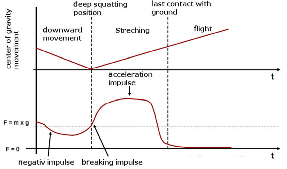
A single jump can be divided into three phases. The first one is downward movement, the second one is stretching and the last one is the flight. It is shown on <imgref image4>.
<imgcaption image4|force-time-graph of a single jump [WAS04]>
 </imgcaption>
As it is shown in the graph, the single jump starts with the downward movement. By bending the knees the impulse on the ground decreases. The stretching is initiated with the beginning of the breaking impulse and the impulse on the ground starts to increase until the flight phase. The foot leaves the ground and the force goes to zero.
Involved muscles and deduction for the demonstrator
Hopping needs a lot of muscle. But for the demonstrator it is not necessary to mention all of the muscles. The muscles which are mentioned are the one which could be considered for being built in the demonstrator. The important ones for a human hopping are the muscle for the foot flexion, the knee extension and the hip extension.
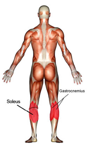
Two important muscles for the foot flexion are the musculus soleus and the musculus gastrocnemius because of their beginning and approach [VAL12].
Musculus soleus has its beginning at dorsal, proximal third of the fibula, in the thirds middle of the tibia and arcus tendineus musculi solei and its approach at the cranial and medial part of the tuber calcanei [VAL12].
Musculus gastrocnemius has its beginning at the condylus medialis and lateralis femoris and its approach cranial and medial part of the tuber calcanei [VAL12].
<imgcaption image5|Musculus soleus and musculus gastrocnemius [www3]>
 </imgcaption>
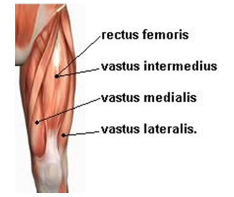
One important muscle for the knee extension is the musculus quadriceps femoris. Musculus quadriceps femoris, [VAL12], it has for heads musculus rectus femoris, musculus vastus medialis, musculus vastus intermedius and musculus vastus laterlis.
<imgcaption image6|Musculus quadriceps femoris with its for heads [www4]>
 </imgcaption>
Musculus rectus femoris has its beginning at the caput rectum ant the spina iliaca anterior inferior and at the caput reflexum at the sulcus supraacetabularis.
Musculus vastus medialis has its beginning at linea aspera, linea intertrochanterica and the tendon of the musculi adductor magnus and longus.
Musculus vastus intermedius has its beginning at upper two-thirds of the femoral shaft. Musculus vastus lateralis has its beginning at the linea aspera of the femoral, trochanter major and linea intertrochanterica.
The approach of all four of them is the ligamentum patellae at the tuberositas tibiae. One important muscle for hip extension is the musculus gluteus maximus. Its beginning dorsal at the os sacrum, fascia thoracolumbalis, ligamentum sacrotuberale, dorsal os ilium and spina iliaca posterior superior and its approach is at the cranial part of the tractus iliotibialis and caudal part of the tuberositas glutea [VAL12].
<imgcaption image7|Musculus gluteus maximus [www5]>
 </imgcaption>
The demonstrator has just one leg, two segments and one motor for keeping the model simple. That means the focus is just on one muscle. The decision fell on musculus rectus femoris. Actually musculus rectus femoris works over two joints, but in this case it is seen as a muscle working over one joint, because we have just one joint at the demonstrator.
Squad
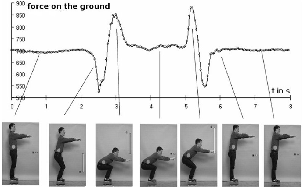
The demonstrator is also able to do a simple downward and upward move without a flight like a squad. A squad is can be divided in different phases, too. <imgref image8> shows it.
<imgcaption image8|Squad phases with forces on the ground [GHS]>
 </imgcaption>
The squad starts with a downward move, force on the ground decrease, because of the second Newtonian axiom. At the end of the downward move the force increases because of the breaking impulse. In the resting position the force becomes the weight of the body and increases by going upwards because of the force which is needed to stretch the knees. After stretching the knees the force decreases under the weight of the body until the velocity is over. The weight increases to the weight of the body again.
Involved muscles and deduction for the demonstrator
The muscles which are used for the squad are almost the same ones like at hopping at chapter „Involved muscles and deduction for the demonstrator“, because the movement is a part of the hopping. The most important ones in this case are musculus quadriceps femoris and musculus gluteus maximus. The deductions for a squad a similar like the deduction for the hopping. Musculus rectus femoris would be the best decision in this case, too, because it has a big part on the squad.